Getting familiar with the TI-99/4A and Floppy Drives

Floppy drives can be pretty confusing and frustrating, especially when they don’t work like you expect. I hope to help clear up some of that. Possibly make it worse, but that’s for you to decide.
Let’s start with some definitions:
Common Floppy Drive Characteristics and abbreviations:
SD = Single Density
DD = Double Density
HD = High Density
QD = Quad Density
SS = Single Sided
DS = Double Sided
Now, you’ll often see description of drives, such as:
SSSD = Single Sided Single Density
DSSD = Double Sided Single Density
DSDD = Double Sided Double Density
DSHD = Double Sided High Density
There are others out there, but those are the most common ones you’ll run across for the TI.
(Under Construction - BUT more to come!)
Introduction:
The TI and the original TI Floppy Disk Controller (TI-FDC) are ONLY capable of SSSD and DSSD modes.
That means that you can only utilize 90k (SS) and 180k (DS) drive capacities.
That DOES NOT mean you can’t use 360k drives, YOU CAN, but the maximum capacity will only be 90k for single-sided, and 180k for double-sided. It will NOT take advantage of the double-density modes that a DSDD drive (360k) can offer. That’s good sorta, because you can use almost any PC compatible 360k drive on the TI.
There is an 80-track upgrade, but that’s for another discussion, as it requires desoldering the old ROM chips and installing upgraded ones. I’m not sure it’s worth the effort. In my opinion there are better ways, to get more bang for your buck.
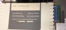
TI Floppy Disk Controller:
1.44MB 3.5” ‘High Density’ drives, will work on the TI, they just won’t work in “high density” mode. With the TI FDC, you’ll still be limited to 90k, and 180k formatting capacity. With a CorComp or Myarc FDC, you can at least double that capacity with the double-density features those controllers provide. Even with those controllers, you’ll be limited to 360k, or DSDD modes, wasting 75% of the disk. But, I still believe it’s great alternative to 5.25” drives for reliability and obtainability. They’re also smaller, quieter, faster, less error prone, more durable, and well... cheaper.
720KB 3.5” Drives; these are your best choice for 3.5” drives in terms of compatibility. However, they pretty much don’t exist anywhere. Good luck finding one or more! Fully compatible with the TI in 90k, and 180k modes.
The biggest issue with 3.5” drives is the shear amount of differences between models and manufacturers. They are also the least documented. Finding datasheets for 3.5” drives is extremely difficult. The variation between same models of same manufacturer vary so dramatically it’s unreal. Teac, for example, must have TWENTY different ‘235HF’ series models and then there’s the ‘235HG’ series, which is no different in quantity of variations. And those are just TWO of their series of 3.5” drives, they have many more.
3.5” Floppy Drives:
Termination, this is where things get interesting. I’ll try my best to explain, but it gets confusing real quick.
All TI-FDC connected drives need to have termination at the end of the “chain”. The chain, is considered the physical cable, and termination is usually done by means of a resistor pack on the last drive of the chain, and NOT on any of the others (in theory).
However! As all rules go, there are exceptions, and it starts to get tricky when that happens. Unfortunately, it’s kind of a guessing game from this point. TI never specified what the nominal termination value is suppose to be (neither did CorComp or Myarc for that matter). One can only assume that it should match what they installed by default, which is not the same as knowing for sure what the engineering design calls for. TI installed a resistor pack (314B151) which is 14-pin 150 Ω resistor DIP pack. CorComp and Myarc never sold drives, so we don’t really know.
Here is where the trouble starts to set in. Different drives from different manufacturers go about terminating their drives in many different ways. When you go to mix and match, you tend to run into troubles. Things seem to no longer fit the ‘rules of engagement’. This is especially true for 3.5” drives, where generally, termination is permanently installed, and no means of determining what the values they used were. If you’re lucky enough to find the datasheet for your exact model, you have half a chance, but thats no easy task. Back to making educated guesses, and trial & error.
The problem with trial and error is; you can actually damage your disk controller with the wrong values, permanently frying an output chip, and that sucks. Don’t get me wrong, it can be fixed, but most people don’t have the tools or knowledge to fix it themselves. So don’t give up if that happens. I can likely do it for you, or any of the other well skilled TI guys on the ‘net. The TI FDC is pretty resilient, but I’ve managed to do it myself. CorComp and Myarc FDC’s are, in my experience, much more finicky than the TI with regard to termination. I’ve also blown the output on my CC and the Myarc is just plain unreliable - I don’t even test with it anymore. I’m glad I never wasted my money on Myarc back in the day. Well, other than the Geneve, but it was just an unreliable as the rest of their stuff.
5.25” drives almost always have removable resisters (but not always) and DIP switches or jumpers for setting the drive up. Back then, it was well known you’d need to change these things to match your system, so they generally included the ability to do so, as well as the documentation. With 3.5” drives, they tended to make a different model for any variation, and eliminated any ability to change that on the drive itself. One of the reasons why most 3.5” drives are permanently set to drive select 2. I’ve never seen a 3.5 with removable resistor pack. Although, I’m sure they made one - for a couple days.
If you’re running into termination issues, which often show up as an inability to format a disk (reads will usually work okay), you’ll want to check your resistor packs (for 5.25” drives) and try to stay within the 150 Ω and 300 Ω range, with no more than 500 Ω total. When I say total, I’m referring to 3.5” drives since you can’t remove the termination on them. In general, 3.5’s are terminated around 500 Ω, when you have two drives in parallel, they come out to 250 Ω (ohms law), which is usually an acceptable number. If you’re mixing 3.5’s with 5.25’s, you’ll have to do the trial and error thing, and more than likely will have to terminate BOTH drives (which goes against the ‘rules’). Stick a 300-500 Ω resistor pack in the 5.25, and it should work. If you stick the original TI 150 Ω resistor pack in, you’ll almost be guaranteed it won’t work right, as you now have ~115 Ω, dangerously low. The formula is;
1/[(1/150)+(1/500)] which equals 115 Ω. Plus you might also end up with termination in the wrong location on the chain. Always test your setup by executing both a format and verification with all drives. Simply doing a read test, will set you up for false indications of success.
There’s SO much more to all this, please be patient until I can add more, hit up Google in the meantime. If you actually got this far, and are still interested in reading more, check out the ‘Floppy User Guide’ in the non-TI downloads above, it’ll give you a greater idea of how complex floppy drives really are.
(Under Construction - BUT more to come!)
Floppy Drive Termination:
Downloadable PDF’s:

Updated Dec. 2, 2018